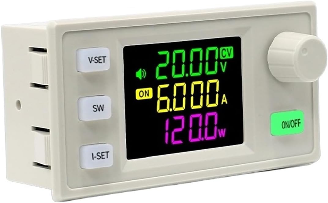
USB Serial bridge for dual-channel Modbus RTU DC power supplies (e.g. SK120X-style modules): 36 V / 6 A per channel. Uses ESP32 or ESP32-C3 and RS485.
No WiFi, no web UI—just a text-based serial protocol for direct computer control.
- USB Serial — Text-based command/response protocol
- Dual channel — Two independent outputs (Modbus slave IDs 1 & 2), 36 V / 6 A per channel
- Fast streaming — Continuous DATA output at configurable rate (50-1000ms)
- Board abstraction (HAL) — One codebase for ESP32 and ESP32-C3
- MCU: ESP32 or ESP32-C3 dev board
- RS485 transceiver (DE/RE optional; enable via build flag)
- Two Modbus RTU power supply units (slave IDs 1 and 2)
| Board | UART | RX | TX | RS485 DE/RE |
|---|---|---|---|---|
| ESP32 (e.g. devkit) | Serial2 | 16 | 17 | 4 |
| ESP32-C3 | Serial1 | 20 | 21 | 3 |
Baud rate: 115200 (both USB CDC and Modbus).
# Build both environments
pio run

# Build for a specific board
pio run -e esp32dev
pio run -e esp32-c3-devkitm-1

# Upload
pio run -t upload
Open Serial Monitor (115200) after upload. The device sends !READY v1.0.0 on boot.
The ESP32 streams data continuously. GUI/scripts send commands to control behavior.
DATA <ch> setV=<v> setA=<a> outV=<v> outA=<a> outP=<p> outE=<e> inV=<v> temp=<t> time=<s> cap=<c> ovp=<v> ocp=<a> opp=<p> status=<s> cvcc=<m> out=<0|1> mppt=<0|1>
ch: Channel number (1 or 2)- Values are raw register values (see Register Map below)
- On read error:
DATA <ch> ... ERR
| Command | Description |
|---|---|
WRITE <ch> <reg> <val> |
Write single register. Response: OK or ERR |
LINK |
Copy Ch1 settings (V, I, output, MPPT) to Ch2. Response: OK or ERR |
STOP |
Stop streaming. Response: OK stopped |
START |
Resume streaming. Response: OK started |
POLL <ms> |
Set poll interval (50-1000ms). Response: OK poll_ms=<ms> |
POLL |
Query current poll interval. Response: OK poll_ms=<ms> |
RAW <ch> |
Dump all 32 registers. Response: RAW <ch> <v0> <v1> ... <v31> |
PING |
Connectivity check. Response: PONG |
REGS |
Print register map |
VERSION |
Firmware version. Response: OK 1.0.0 |
ch: 1 or 2reg/val: decimal or hex (0xprefix)
!READY v1.0.0
DATA 1 setV=1200 setA=3000 outV=1198 outA=1500 outP=1797 outE=0 inV=2400 temp=381 time=0 cap=0 ovp=3700 ocp=6100 opp=25000 status=0 cvcc=0 out=1 mppt=0
DATA 2 setV=1200 setA=3000 outV=1195 outA=1480 outP=1768 outE=0 inV=2400 temp=378 time=0 cap=0 ovp=3700 ocp=6100 opp=25000 status=0 cvcc=0 out=1 mppt=0
> STOP
OK stopped
> WRITE 1 0x0000 1400
OK
DATA 1 setV=1400 ...
> POLL 200
OK poll_ms=200
> START
OK started
| Reg | Name | Unit | R/W |
|---|---|---|---|
| 0x0000 | setV | V * 100 | R/W |
| 0x0001 | setA | A * 1000 | R/W |
| 0x0002 | outV | V * 100 | R |
| 0x0003 | outA | A * 1000 | R |
| 0x0004 | outP | W * 100 | R |
| 0x0005 | outE_H | Wh (high) | R |
| 0x0006 | outE_L | Wh (low) | R |
| 0x0007 | inV | V * 100 | R |
| 0x000D | temp | °C * 10 | R |
| 0x0009 | time_H | sec (high) | R |
| 0x000A | time_L | sec (low) | R |
| 0x000B | cap_H | Ah*1000 (h) | R |
| 0x000C | cap_L | Ah*1000 (l) | R |
| 0x000E | OVP | V * 100 | R/W |
| 0x000F | OCP | A * 1000 | R/W |
| 0x0010 | OPP | W * 100 | R/W |
| 0x0012 | out | 0/1 | R/W |
| 0x0013 | status | flags | R |
| 0x0014 | cvcc | 0=CV, 1=CC | R |
| 0x001F | mppt | 0/1 (exp) | R/W |
Standalone SDL2 control panel for the PSU with:
- VFD display — Voltage, current, power readouts with green-on-black style
- Bar meters & temperature — Voltage/current bars and temp strip (full GUI)
- Scope traces — Real-time voltage/current waveform per channel
- Controls — OUTPUT toggle, voltage/current setpoints, keypad (full GUI)
- Dual vs single —
psu_gui/psu_gui_toolbar(two channels);psu_gui_single/psu_gui_toolbar_single(channel 1 only) - TRACKING — Link Ch1 settings to Ch2 (dual full GUI only)
- Demo mode — Runs with simulated data if serial port unavailable
Screenshots (canonical copies in docs/images/psu-gui/; duplicates in psu-gui/screenshots/). More detail: psu-gui/README.md.
Dual full GUI (psu_gui)

Single full GUI (psu_gui_single)

Dual toolbar (psu_gui_toolbar)

# Ubuntu/Debian
sudo apt install libsdl2-dev libsdl2-ttf-dev

# Fedora
sudo dnf install SDL2-devel SDL2_ttf-devel

# Arch
sudo pacman -S sdl2 sdl2_ttf
Also needs a monospace font (DejaVu Sans Mono or Liberation Mono).
cd psu-gui
make

# With ESP32 connected
./psu_gui /dev/ttyUSB0

# Demo mode (no device)
./psu_gui

# Compact toolbar-style GUI (dual channel)
./psu_gui_toolbar /dev/ttyUSB0
./psu_gui_toolbar

# Single-channel variants (hardware channel 1 only)
./psu_gui_single /dev/ttyUSB0
./psu_gui_toolbar_single /dev/ttyUSB0- OUTPUT button — Toggle output on/off
- VOLTAGE/CURRENT inputs — Click to edit, type value, press SET or Enter
- TRACKING — When enabled, copies Ch1 settings to Ch2
- REFRESH — Force status poll
Toolbar GUI (psu_gui_toolbar): Compact strip with large V/A readouts, ON/OFF and CV/CC status. SET opens a modal to edit setpoints (click outside, CANCEL, or Esc to close)
src/main.cpp— Serial protocol, DATA streaming, command parsersrc/hal/— Board HAL: UART/RS485 pins, initsrc/modbus_psu.h/modbus_psu.cpp— Register map, Modbus read/writepsu-gui/— SDL2 GUI applicationmain.c— Full dual-channel GUImain_single.c— Full single-channel GUImain_toolbar.c— Compact dual-channel toolbarmain_toolbar_single.c— Compact single-channel toolbarserial_port.c/h— Linux serial port abstractionpsu_protocol.c/h— PSU command/response parsing
import serial
import time
import re

ser = serial.Serial('/dev/ttyUSB0', 115200, timeout=1)
time.sleep(2)  # wait for ESP32 boot

# Wait for READY
while True:
    line = ser.readline().decode().strip()
    if line == '!READY':
        break

# Stop streaming to send commands
ser.write(b'STOP\n')
ser.readline()  # OK stopped

# Set voltage to 15.00V on channel 1
ser.write(b'WRITE 1 0x0000 1500\n')
print(ser.readline().decode().strip())  # OK

# Resume streaming and read data
ser.write(b'START\n')
ser.readline()  # OK started

# Parse DATA lines
for _ in range(10):
    line = ser.readline().decode().strip()
    if line.startswith('DATA'):
        m = re.search(r'outV=(\d+)', line)
        if m:
            print(f"Output voltage: {int(m.group(1)) / 100:.2f} V")

ser.close()By default, RS485 DE/RE control is disabled. To enable:
# In platformio.ini, add to build_flags:
build_flags =
-DUSE_RS485_DIR=1- MPPT — Experimental; support depends on PSU firmware.
- Values are raw register values (setV 1200 = 12.00 V, setA 3000 = 3.000 A, etc.)
- Single-threaded Arduino environment;
modbus_psu_meaning()/modbus_psu_interpret()use static buffers.
- SK120X DC Power Supply (Amazon)
- Modbus library: lahirunirmalx/ModbusMaster
MIT — use, modify, and share.