                          ███╗   ██╗██╗████████╗██████╗  ██████╗        █████╗
                          ████╗  ██║██║╚══██╔══╝██╔══██╗██╔═══██╗      ██╔══██╗
                          ██╔██╗ ██║██║   ██║   ██████╔╝██║   ██║█████╗╚█████╔╝
                          ██║╚██╗██║██║   ██║   ██╔══██╗██║   ██║╚════╝██╔══██╗
                          ██║ ╚████║██║   ██║   ██║  ██║╚██████╔╝      ╚█████╔╝
                          ╚═╝  ╚═══╝╚═╝   ╚═╝   ╚═╝  ╚═╝ ╚═════╝        ╚════╝





Nitro-8 is a fully functional 8-bit CPU designed and built entirely from scratch in Logisim Evolution — featuring a hardwired ALU, custom 16-instruction ISA, banked ROM, 256-byte RAM, a 16×16 RGB pixel display, and a modular 20-unit sprite storage system.
- Overview
- Features
- Architecture
- Live Simulation
- Circuit Overview
- Instruction Set
- RGB Display
- Storage System
- Python Assembler
- Demo Programs
- Build Order
- Tools Used
- Project Structure
- Author
- License
Nitro-8 is a custom 8-bit processor built entirely from logic gates up — no shortcuts, no black-box components. Every subsystem, from the half adder at the bottom of the ALU to the MUX-driven sprite storage at the top, was constructed and verified gate by gate inside Logisim Evolution.
The CPU can fetch, decode, and execute real assembly instructions, perform arithmetic and bitwise operations, read and write memory, and render pixel-art graphics on a live 16×16 RGB display — all in a single integrated circuit.
Built as part of a Computer Architecture course at NFC IET Multan, this project demonstrates end-to-end understanding of digital logic, processor microarchitecture, memory systems, and low-level programming.
| Category | Capability |
|---|---|
| ALU | ADD, SUB, AND, OR, XOR, NOT, SHL, SHR — all 8-bit |
| Registers | RegA, RegB — two general-purpose 8-bit registers |
| Program Counter | 8-bit PC with increment, load, and synchronous reset |
| Instruction Register | 16-bit IR with opcode / operand split |
| Control Unit | Hardwired, decodes 16+ instructions into micro-signals |
| RAM | 256 × 8 read/write data memory |
| ROM | 2048 × 16 banked program memory with SETBANK switching |
| Video | 16×16 RGB display, XTerm256 8-bit color, direct pixel write |
| Storage | 20 independent Sprite Unit ROMs, MUX-selected |
| Assembler | Custom Python assembler → Logisim ROM hex format |
| Control Flow | JMP, JZ (conditional), HLT, NOP |
| Reset | Full synchronous reset across all registers and memory |
┌─────────────────────────────────────────────────────────────────┐
│                         NITRO-8 CPU                             │
│                                                                 │
│   Clock ──► PC ──► ROM / Storage ──► IR ──► Control Unit       │
│                                                   │             │
│                              ┌────────────────────┘             │
│                              ▼                                  │
│                        RegA ──► ALU ◄── RegB                    │
│                              │                                  │
│                    ┌─────────┴──────────┐                       │
│                    ▼                    ▼                       │
│             VideoRAM ──► RGB Display   RAM (data)               │
└─────────────────────────────────────────────────────────────────┘
- Half Adder → Full Adder → 8-bit Ripple Carry Adder
- 8-bit ALU (8 operations)
- 8-bit D flip-flop Register × 2
- 8-bit Program Counter (inc / load / reset)
- 16-bit Instruction Register (opcode + operand split)
- Hardwired Control Unit (16 instructions)
- RAM8 — 256×8 synchronous read/write
- ROM8 — 2048×16 with bank switching
- VideoRAM — direct pixel write to RGB Video component
- Storage System — 20 Unit ROMs, 5-bit MUX selection
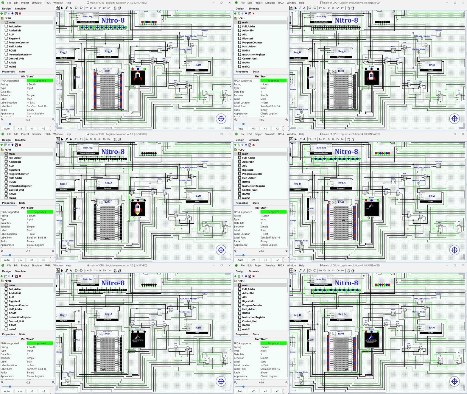
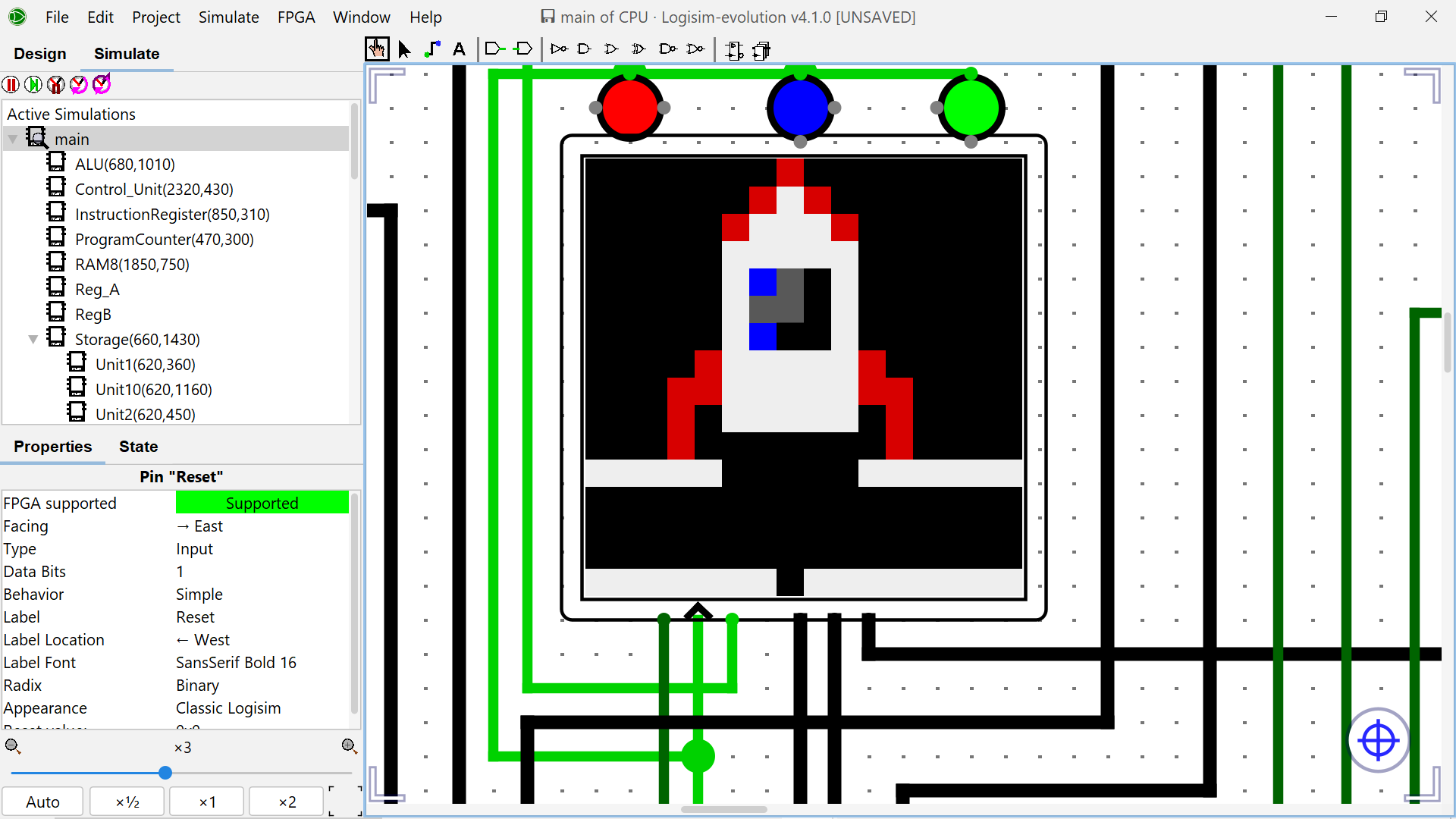
Nitro-8 live simulation — the CPU fetching, decoding, and executing sprite programs, cycling through all 20 Storage Units and painting pixel art on the 16×16 RGB display.
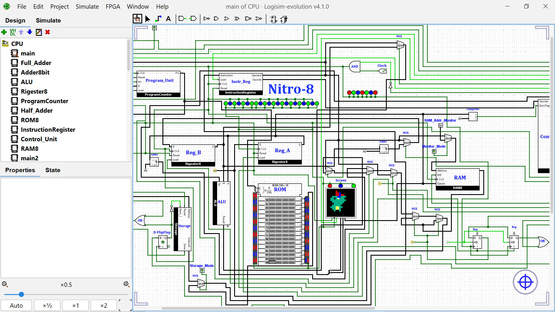
Complete Nitro-8 CPU — ALU, registers, PC, ROM, RAM, control unit, and video display, all wired and running.
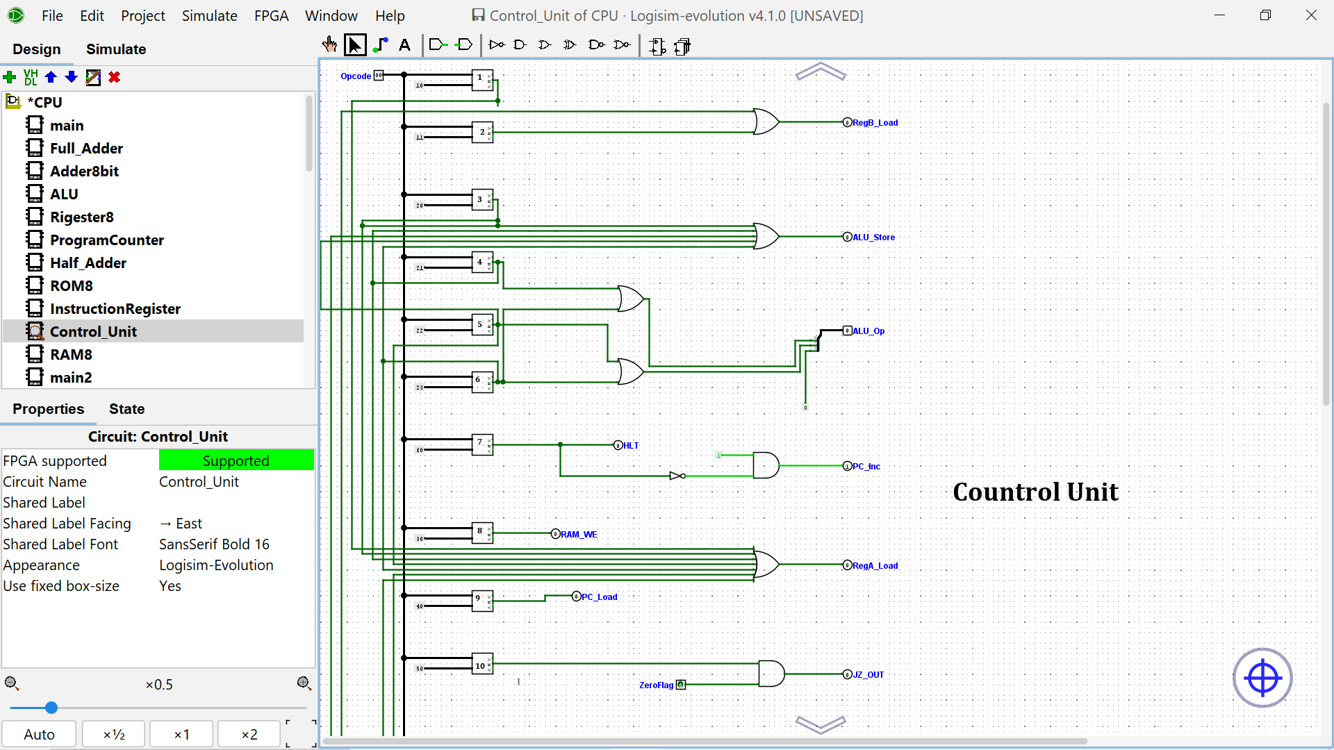 Hardwired Control Unit decoding 16+ instructions into micro-control signals |
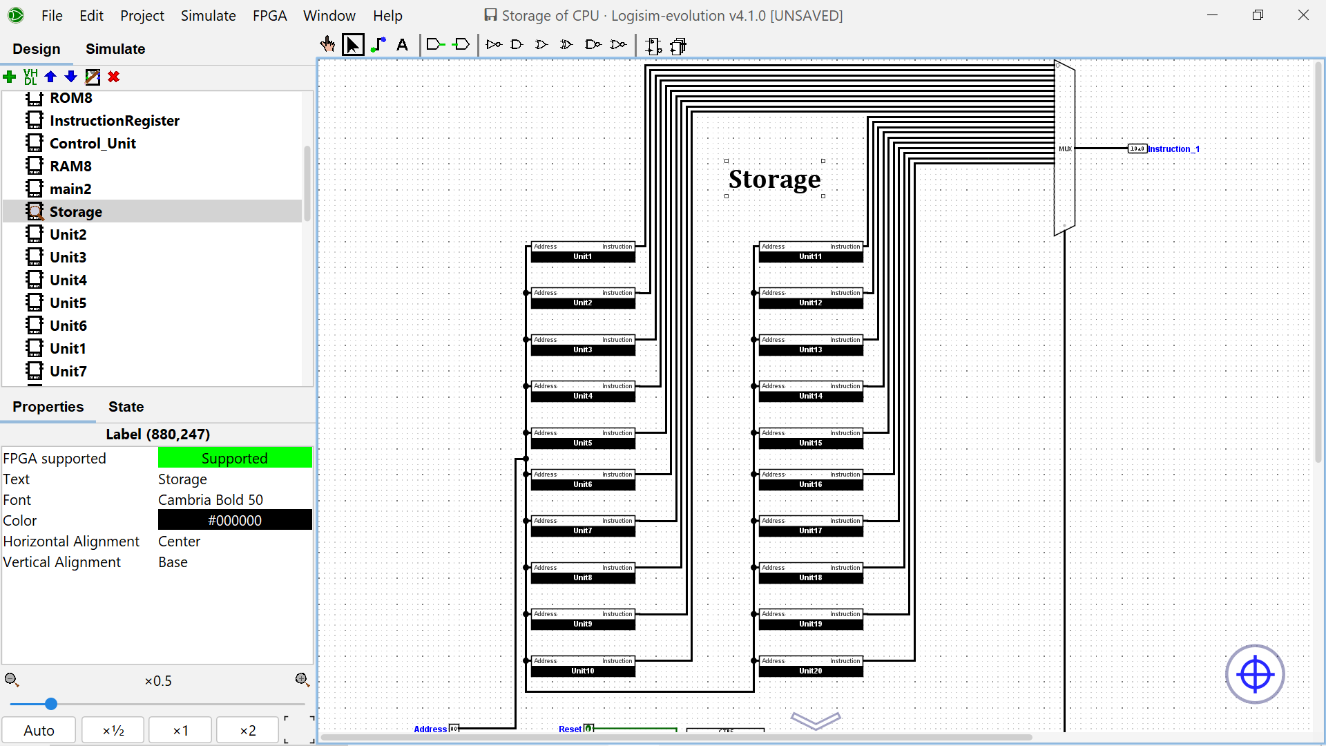 20-Unit Sprite Storage System with MUX-based selection |
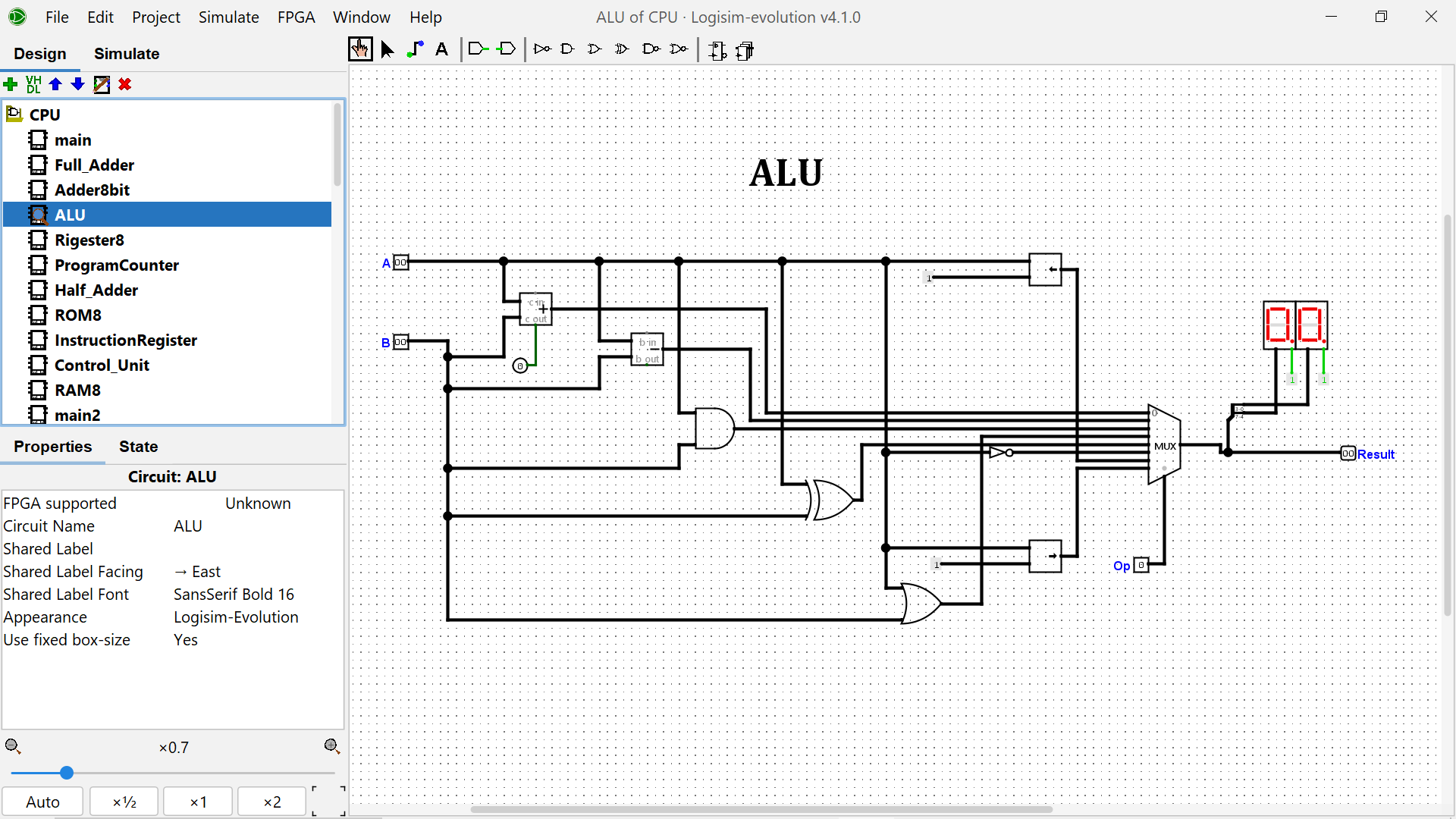 8-bit ALU performing arithmetic and logic operations |
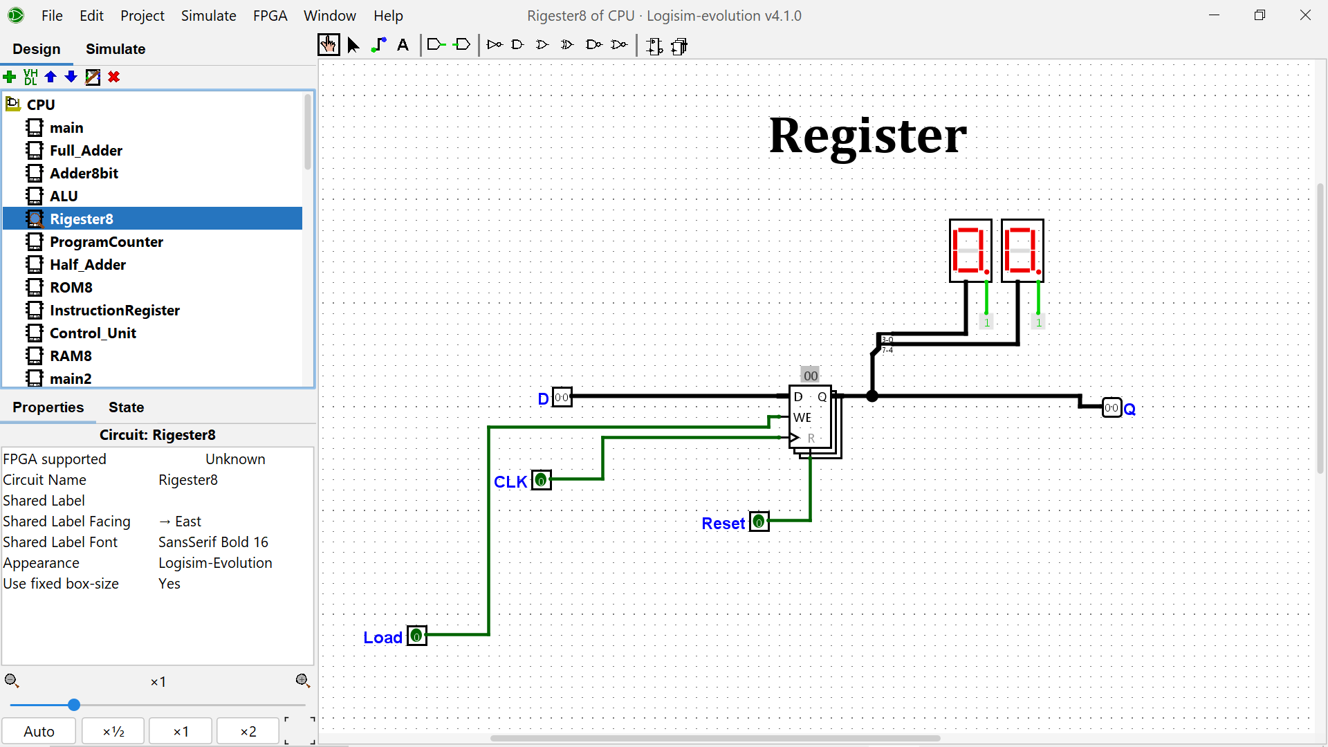 8-bit D flip-flop based register |
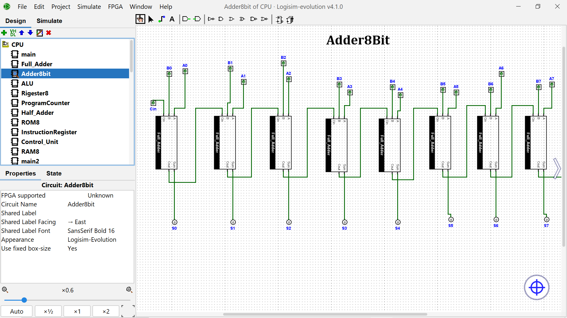 8-bit Ripple Carry Adder built from full adder chains |
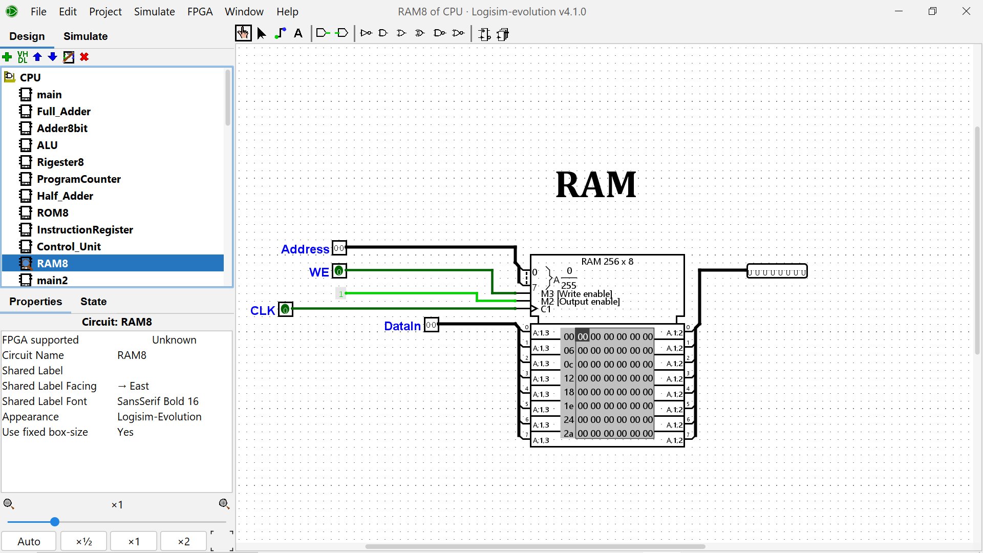 256×8 synchronous RAM with read/write support |
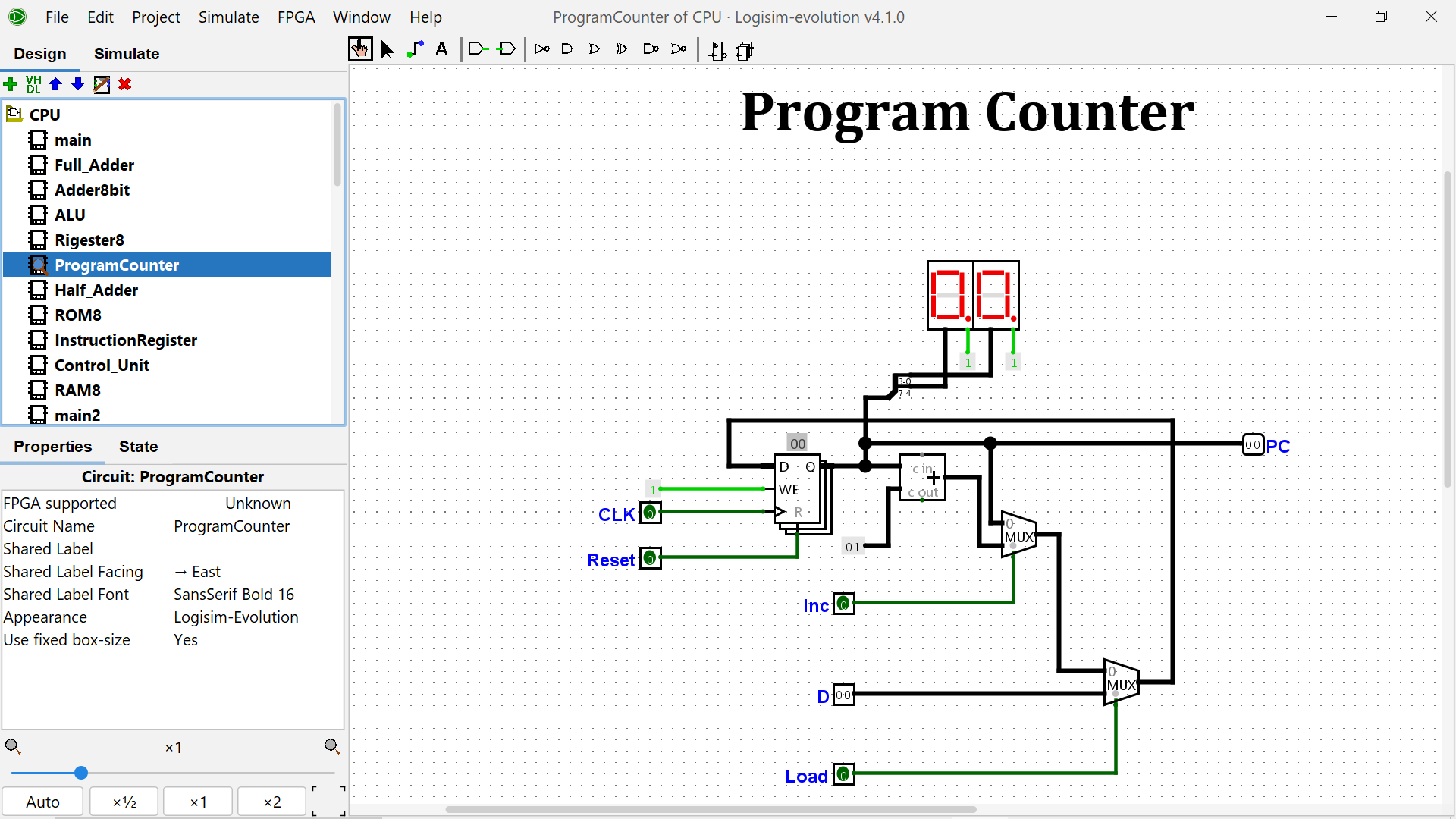 8-bit Program Counter with increment, load, and synchronous reset |
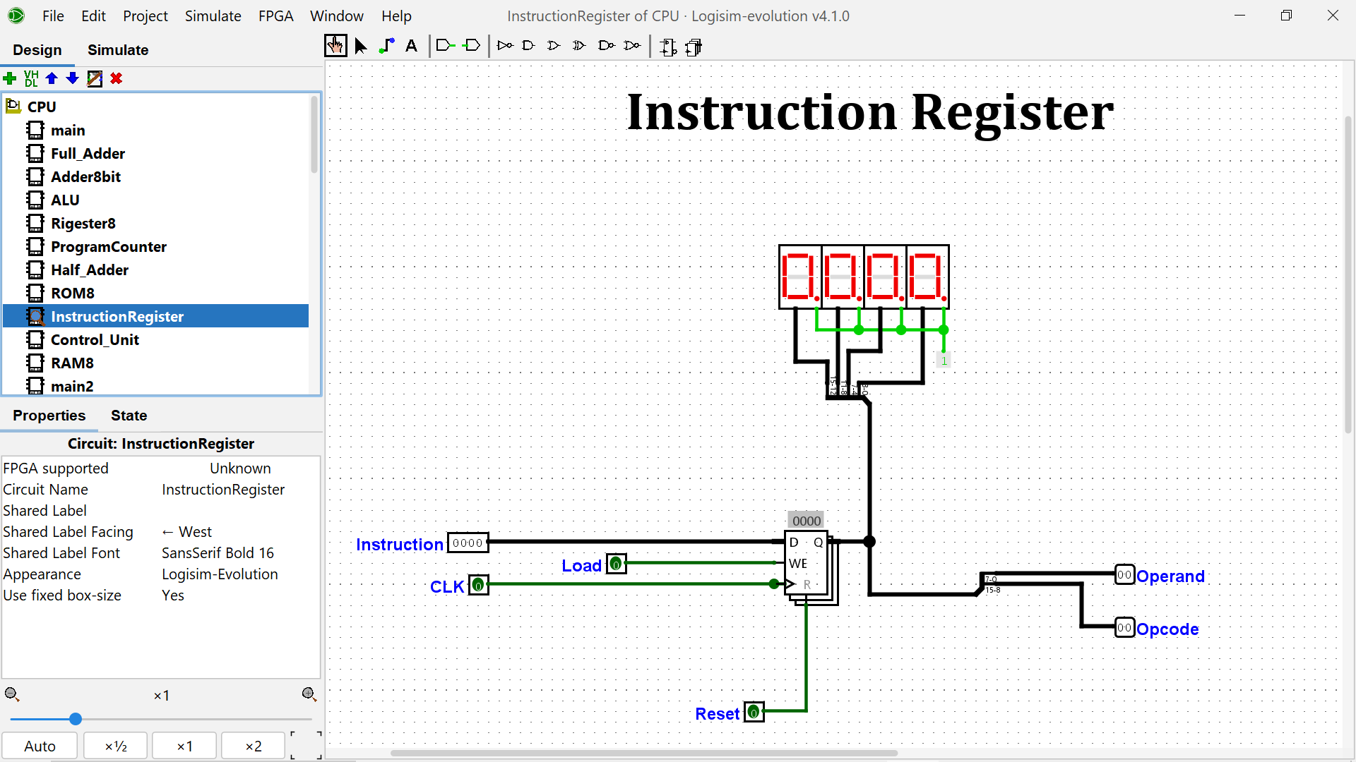 16-bit Instruction Register splitting opcode and operand |
| Opcode | Mnemonic | Operation |
|---|---|---|
10nn |
LOAD_A n |
RegA ← n |
11nn |
LOAD_B n |
RegB ← n |
2000 |
ADD |
RegA ← RegA + RegB |
2100 |
SUB |
RegA ← RegA − RegB |
2200 |
AND |
RegA ← RegA AND RegB |
2300 |
OR |
RegA ← RegA OR RegB |
30nn |
STORE n |
RAM[n] ← RegA |
40nn |
JMP n |
PC ← n |
50nn |
JZ n |
if RegA = 0 → PC ← n |
60nn |
VSTORE n |
VideoRAM[n] ← RegA (color) |
6100 |
VSTORE_B |
VideoRAM[RegB] ← RegA |
7000 |
INC |
RegA ← RegA + 1 |
7100 |
INC_B |
RegB ← RegB + 1 |
80nn |
LOAD_RAM n |
RegA ← RAM[n] |
90nn |
SETBANK n |
ROM bank ← n |
F000 |
HLT |
Halt execution |
0000 |
NOP |
No operation |
The Nitro-8 drives a 16×16 pixel RGB display using Logisim Evolution's RGB Video component in XTerm256 8-bit color mode, giving 256 distinct colors addressable by a single byte.
Pixel addressing:
Address = (row − 1) × 16 + (col − 1)
Row 1, Col 1 → 0x00      Row 16, Col 16 → 0xFF
Programs rendered on the display:
- Alphabet letters — N, I, T, R, O, 8
- Pixel-art sprites — heart, robot, rocket, car
- Rainbow stripe fill
- Checkerboard and border patterns
- Diagonal X pattern
The Storage subsystem contains 20 independent Unit ROMs. Each Unit holds one complete sprite or letter program. A 5-bit counter advances the active Unit via a MUX — when one program halts, the next Unit fires automatically.
Storage
├── Unit 01  — Letter N
├── Unit 02  — Letter I
├── Unit 03  — Letter T
├── Unit 04  — Letter R
├── Unit 05  — Letter O
├── Unit 06  — Letter 8
├── Unit 07  — Sprite (expandable)
├── ...
└── Unit 20  — (expandable)
The project ships a Python assembler that compiles human-readable Nitro-8 assembly into the hex format expected by Logisim's ROM editor.
python assembler.pyInput → Output example:
; Source
LOAD_A 05
LOAD_B 03
ADD
HLT
; ROM hex output
1005 0000 1103 0000 2000 0000 F000 0000
0000 0000 0000 0000 ... (padded to 256 entries)
NOPs are automatically inserted between instructions to satisfy the CPU's fetch cycle, and output is zero-padded to 256 entries for direct paste into the Logisim ROM editor.
5 + 3 = 8 (arithmetic)
LOAD_A 05
LOAD_B 03
ADD
HLT
Countdown 5 → 0 (loop + branch)
LOAD_A 05
LOAD_B 01
SUB          ; RegA = RegA - 1
JZ   0B      ; if zero → halt
JMP  02      ; else loop
HLT
Draw pink heart (VSTORE pixel painting)
LOAD_A D3    ; XTerm256 pink
VSTORE 34
VSTORE 35
VSTORE 37
VSTORE 38
; ... remaining pixel addresses
HLTThe CPU was assembled incrementally, each layer verified before the next was added:
 1  Half Adder               11  RAM
 2  Full Adder               12  JMP + JZ instructions
 3  8-bit Ripple Carry Adder 13  RGB Video Display
 4  ALU                      14  VSTORE + VSTORE_B
 5  8-bit Register           15  INC + INC_B
 6  Program Counter          16  LOAD_RAM
 7  ROM                      17  SETBANK + bank switching
 8  Instruction Register     18  Storage system (20 Units)
 9  Control Unit             19  Python assembler
10  Main CPU integration
| Tool | Version | Purpose |
|---|---|---|
| Logisim Evolution | v4.1.0 | Circuit design & simulation |
| Python | 3.x | Custom assembler |
| Git | — | Version control |
| GitHub | — | Hosting & CDN asset delivery |
Nitro-8/
├── CPU.circ                  ← Main Logisim circuit
├── assembler.py              ← Python assembler
├── README.md
├── assets/
│   ├── demo/
│   │   └── demo1.gif         ← Live simulation recording
│   └── screenshots/
│       ├── main.png          ← Full CPU circuit
│       ├── ControlUnit.png   ← Hardwired control unit
│       ├── StorageUnit.png   ← 20-unit sprite storage
│       └── Screen.png        ← RGB display output
└── programs/                 ← Assembly programs (coming soon)
Noman Rafique (Nomi)
BS Artificial Intelligence · NFC IET Multan, Pakistan Semester 2 · GPA 4.0 / 4.0


This project is open source and available under the MIT License.
Built with patience, logic gates, and a lot of debugging. 🧠
